

WeMos D1 WiFi UNO Based ESP8266
370.00 EGP
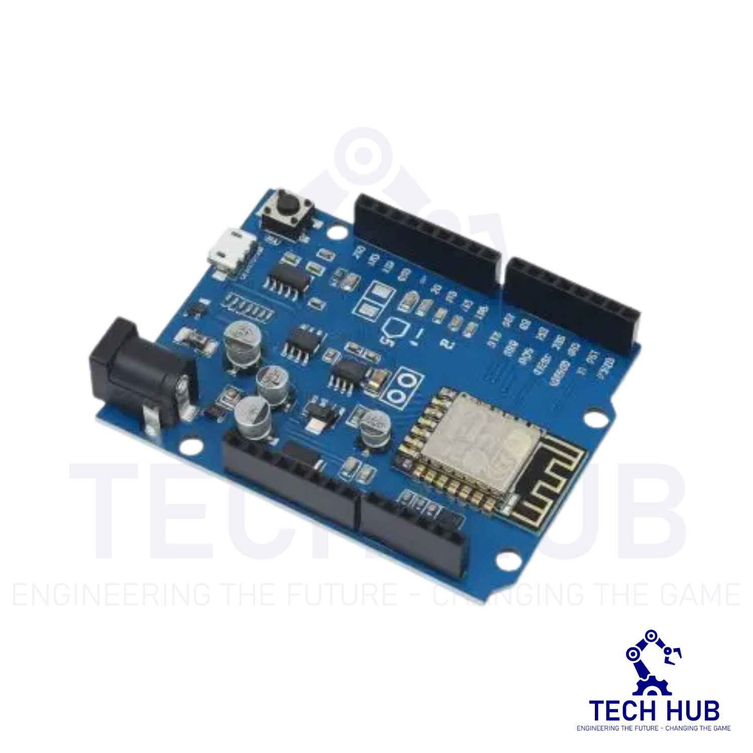
The ESP8266 D1 R1 WiFi board utilizes the ESP8266 WiFi enabled processor, and puts it onto an Arduino Uno board footprint. It provides a way to work with the ESP8266 in a familiar setup and does not require a breadboard in order to make interconnections since it has the typical on-board female headers. It will also work with some Uno shields that have compatible I/O pin-outs.
5 in stock
Description
ESP8266 D1 R1 WiFi Processor with Uno Footprint
The ESP8266 D1 R1 WiFi board utilizes the ESP8266 WiFi enabled processor, and puts it onto an Arduino Uno board footprint. It provides a way to work with the ESP8266 in a familiar setup and does not require a breadboard in order to make interconnections since it has the typical on-board female headers. It will also work with some Uno shields that have compatible I/O pin-outs.
KEY FEATURES OF ESP8266 D1 R1:
- Microcontroller: ESP-8266 32-bit
- Clock Speed: 80MHz and up to 160MHz
- USB Converter: iFT232-S16
- Operating Voltage: 3.3V
- Flash Memory: 4MB
- Digital I/O: 11
- Analog Inputs: 1
- Communications: I2C, Serial, SPI
- WiFi: Built-in
Besides adding WiFi capability, the main claim to fame for the ESP8266 processor over the AVR processor of the standard Arduino is that it has a larger 4MB of Flash memory and runs at clock speeds of 80MHz and can sometimes optionally be overclocked to 160MHz and has a very fast processing speed.
The Digital I/O except for D0 all support PWM and interrupts. In addition they can be configured to have pull-up or pull-down resistors On the down-side, it has only 1 analog input which is probably the most significant limitation. That can always be overcome by using an external Analog Mux module like our 16-channel 74HC4067, ADS1115 4-Channel 16-bit ADC or the MCP3008-I/P 8 channel A/D converter IC below if more analog I/O is desired.
Per spec, the digital I/O is limited to 3.3V, but the ESP-8266 mfr has made statements that the digital pins are in fact 5V tolerant and there are many installations using the module directly connected to the logic lines of 5V peripherals.
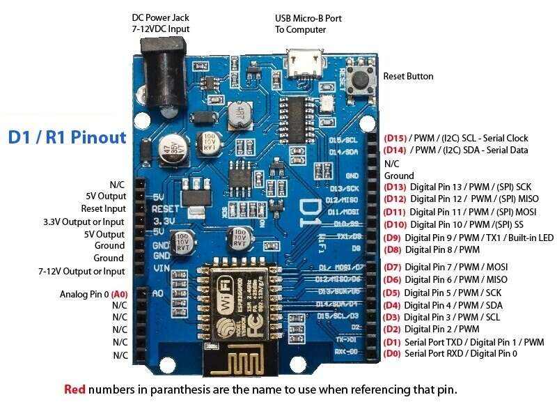
Note that when programming the board, you need to refer to the I/O using both the letter and number. With Arduino, output D3 would be referred to simply as ‘3’, but with the D1 board, you need to refer to the pin as ‘D3’.
The board can be powered via the USB port or using an external 7-12V power supply via the DC Power Jack. The board runs at 3.3V, so keep that in mind when working with I/O.
TECHNICAL SPECIFICATIONS
| Microcontroller | ESP8266 32-bit |
| Serial to USB Converter | iFT232-S16 |
| Operating Voltage | 3.3V |
| Input Voltage (recommended) | 7-12V |
| Digital I/O Pins | 11 |
| PWM I/O Pins (Shared with Digital I/O) | 10 |
| Analog Input Pins | 1 (10-bit) |
| DC Current per I/O Pin | 12mA (Max) |
| Hardware Serial Ports | 1 |
| Flash Memory | 4 MBytes |
| Instruction RAM | 64 KBytes |
| Data RAM | 96 KBytes |
| Clock Speed | 80MHz |
| Network | IEEE 802.11 b/g/n WiFi |
| Built-in LED | Attached to digital pin 13 |
| USB Connector Style | Micro-B Female |
| Board Dimensions (PCB) | 69 x 53mm |
Pin Out
|
Pin |
Function |
ESP-8266 Pin |
|
TX |
TXD |
TXD |
|
RX |
RXD |
RXD |
|
A0 |
Analog input, max 3.3V input |
A0 |
|
D0 |
IO |
GPIO16 |
|
D1 |
IO, SCL |
GPIO5 |
|
D2 |
IO, SDA |
GPIO4 |
|
D3 |
IO,Pull-up |
GPIO0 |
|
D4 |
IO,pull-up, BUILTIN_LED |
GPIO2 |
|
D5 |
IO, SCK |
GPIO14 |
|
D6 |
IO, MISO |
GPIO12 |
|
D7 |
IO, MOSI |
GPIO13 |
|
D8 |
IO,pull-down, SS |
GPIO15 |
|
G |
Gound |
GND |
|
5V |
5V |
– |
|
3V3 |
3.3V |
3.3V |
|
RST |
Reset |
RST |
*All IO have interrupt/pwm/I2C/one-wire supported(except D0)
Note: All IO is work at 3.3V.
Useful links
Reviews (0)
Related products
Sold out
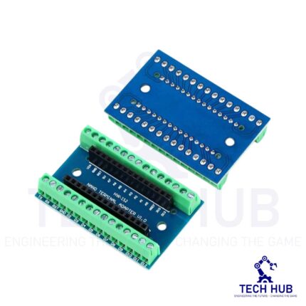
Arduino NANO Screw Terminal Expansion Board Shield
- Screw Terminal Shield for Arduino Nano Family.
- Compatible with Arduino Nano, Arduino Nano 33 IoT, Arduino Nano RP2040 Connect, Arduino Nano 33 BLE Sense, Arduino Nano 33 BLE, Arduino Nano Every, Arduino Nano ESP32
- Simplifies DIY projects by providing easy-to-use screw terminals.
- Color: blue
- Allows convenient and secure connections for Arduino Nano Applications.
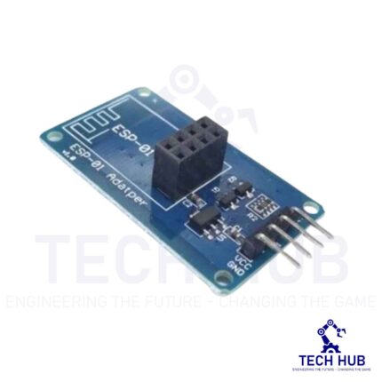
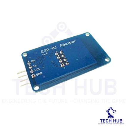
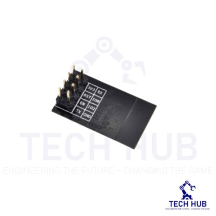
WIFI Serial Module ESP-01 Adapter Board (3.3V 5V)
The use of an ESP8266 with Arduino requires logic level translation of the UART signal, as provided by this easy 3.3 V – 5 V adapter. It makes the ESP-01 ESP8266 WiFi module the easiest WiFi transceiver for your Arduino (5 V).



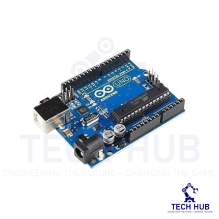

Arduino UNO R3
"Uno" means one in Italian and was chosen to mark the release of Arduino Software (IDE) 1.0. The Uno board and version 1.0 of Arduino Software (IDE) were the reference versions of Arduino, now evolved to newer releases. The Uno board is the first in a series of USB Arduino boards, and the reference model for the Arduino platform; for an extensive list of current, past or outdated boards see the Arduino index of boards.
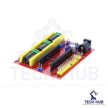
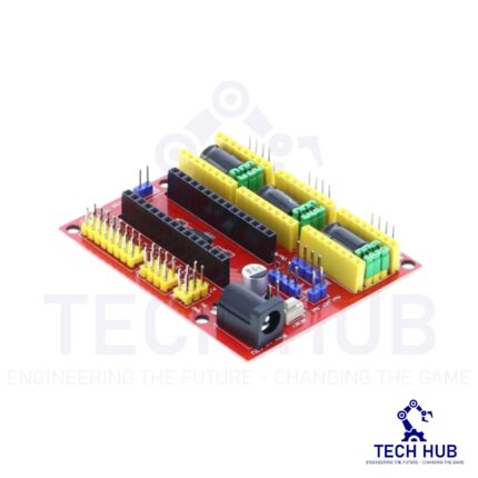
Arduino Shield – Nano CNC Machine V4 Board
This board is widely used for driver expansion board of engraving machines. There are a total 3 3-way slots for stepper motor driver modules (Model A4988 or Drv8825 - It sold separately at our store), and it can drive 3-way stepper motors each up to 2A. Each way stepper motor has two I/O ports and it means 6 I/O ports can manage 3 stepper motors. It is very convenient to operate.
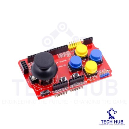
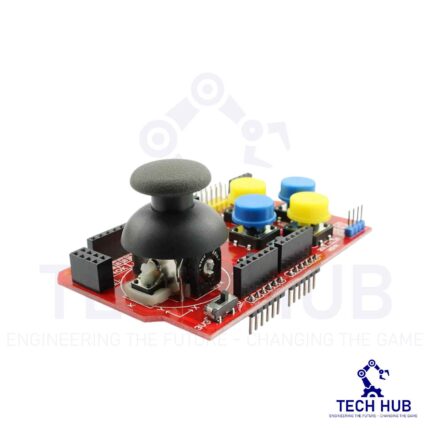
Arduino Joystick Shield
- Compatibility: Designed for use with Arduino boards.
- Joystick: Features a two-axis joystick for precise control in both X and Y directions.
- Buttons: Equipped with multiple push buttons for additional input options.
- Shield Form Factor: Designed to be easily mounted onto Arduino boards, providing a convenient and compact form factor.
Reviews
There are no reviews yet.