

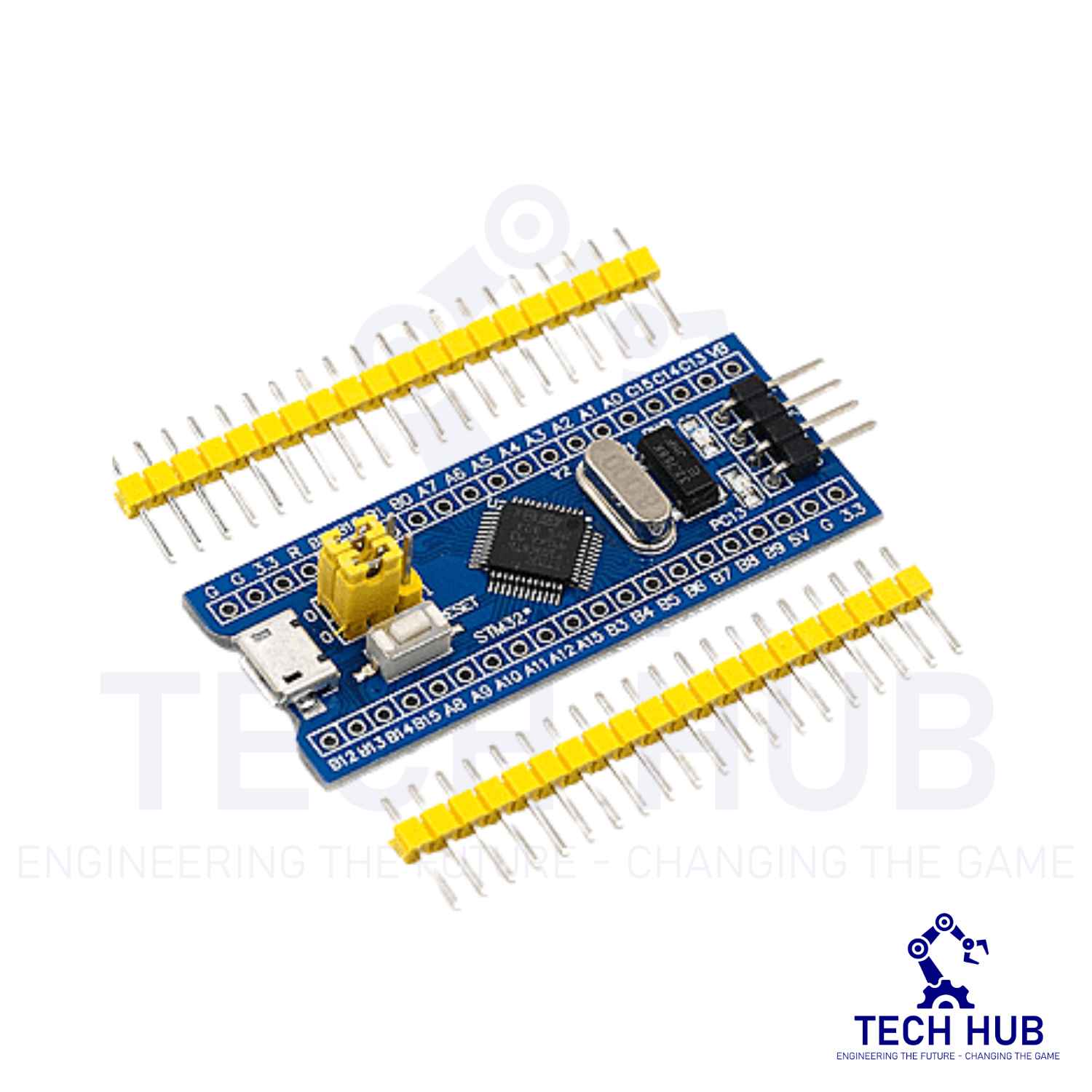
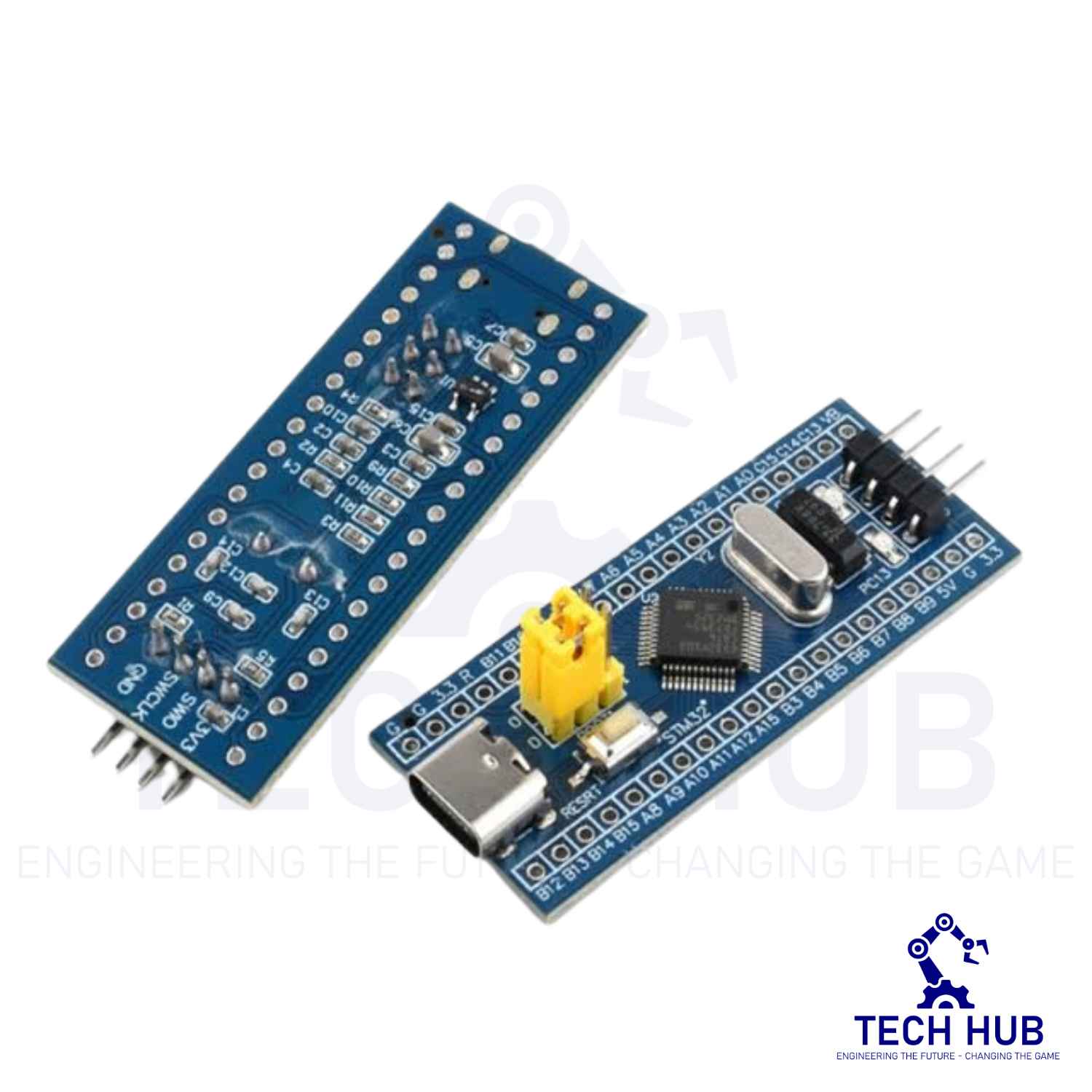


STM32F103C8T6 ARM STM32 Minimum System Development Board
250.00 EGP
- Number of pins: 48
- Kernel: ARM Cortex-M3
- Operating frequency: 72MHz
- Storage resources: 64K Byte Flash, 20KByte SRAM
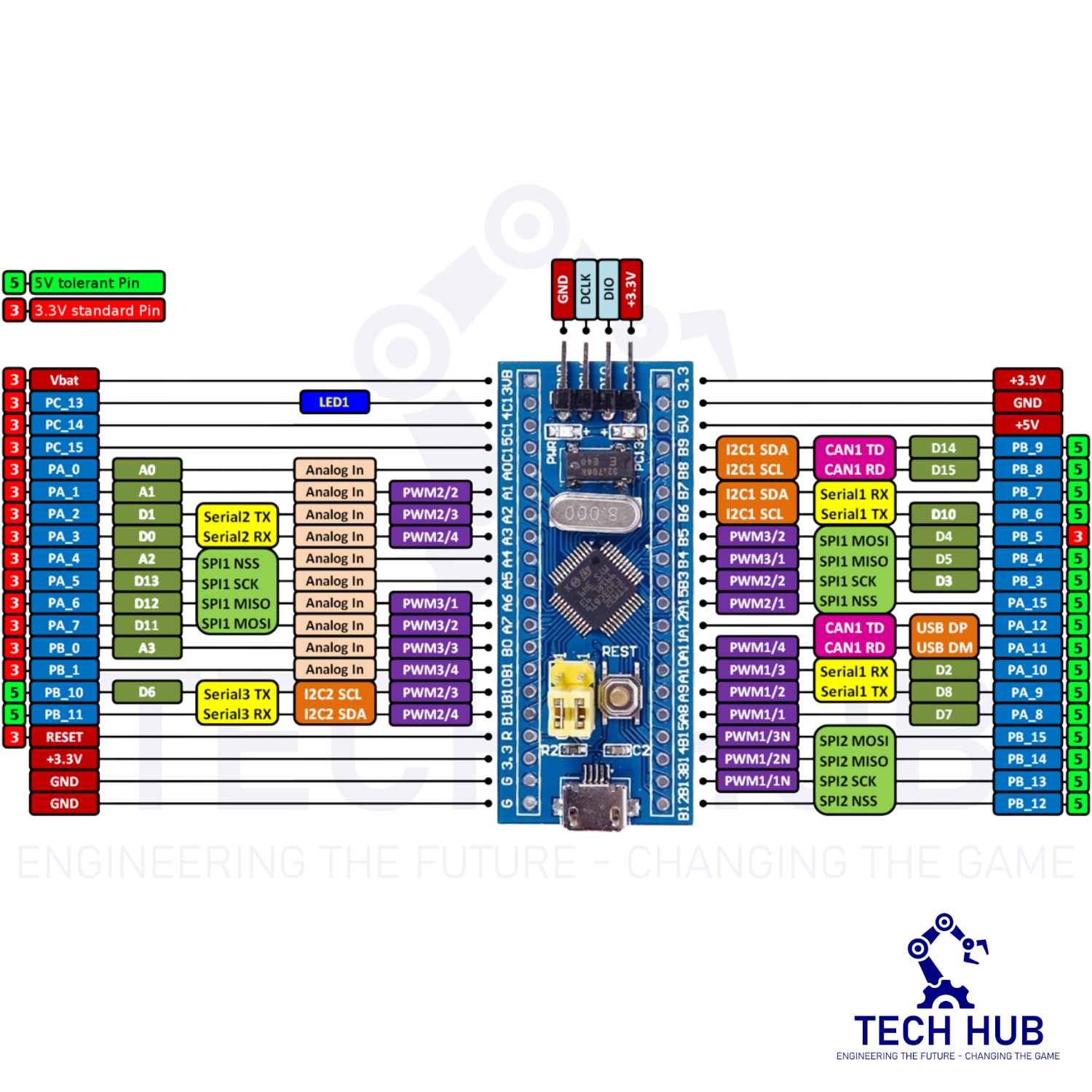
- Interface Resources: 2x SPI, 3x USART, 2x I2C, 1x CAN, 37x I / O ports,
- Analog-to-digital conversion: 2x ADC (12-bit / 16-channel)
- Timers: 3 general timers and 1 advanced timer
- Debug Download: Support JTAG / SWD debug interface to download, support for IAP.
- RT9193: 3.3V regulator chip, a maximum output of 300mA.
66 in stock
Description
Product Introduction
This is a core chip based on STM32F103C8T6 ARM core board.
Features:
- The board is based on the most basic MCU circuit, 8Mhz crystal circuit, and USB power supply circuit.
- The core board is divided into two rows leading to all the I / O ports.
- With SWD simulation debug download interface, simple and convenient, debugging speed.
- The use of the Mirco USB interface, you can do USB communication and power supply, The USB interface, is compatible with the ordinary mobile phone charger interface.
- RTC Crystal is easy to start and more stable.
- Keil can be used to compile, and IAR compile can be downloaded through the JLink or USART1 procedures, the procedures are the owner and debugging procedures.
Chip Description:
- STM32F103C8T6
- Package Type: LQFP
- Number of pins: 48
- Kernel: ARM Cortex-M3
- Operating frequency: 72MHz
- Storage resources: 64K Byte Flash, 20KByte SRAM
- Interface Resources: 2x SPI, 3x USART, 2x I2C, 1x CAN, 37x I / O ports,
- Analog-to-digital conversion: 2x ADC (12-bit / 16-channel)
- Timers: 3 general timers and 1 advanced timer
- Debug Download: Support JTAG / SWD debug interface to download, support for IAP.
- RT9193: 3.3V regulator chip, a maximum output of 300mA.
Interface Description:
- SWD interface: support for simulation, download and debug.
- Mirco USB interface: power supply and USB communication, do not support the download.
- USART1 interface: USART1 can be used to download the program, or use the USART1 for communication.
- MCU pin interface: leads all I / O port pins, easy to connect with peripherals.
- 5, 5V, and 3.3V power input and output interface: commonly used in external power supply, or with other modules for common ground treatment.
Other Device Description:
- Power LED (PWR): Power indicator status, can determine whether the power supply is stable.
- The user LED (PC13): to facilitate the I / O output test or indicate the program running.
- Start jumping choose programming mode: (1, the user flash memory 2, SRAM 3, system memory).
- Reset button: reset chip for the user program.
- 8M Crystal: The frequency can be set to make the system clocked at 72MHz.
- 32.768KHz Crystal: Available for built-in RTC, or for calibration.
Reviews (0)
Related products
Sold out
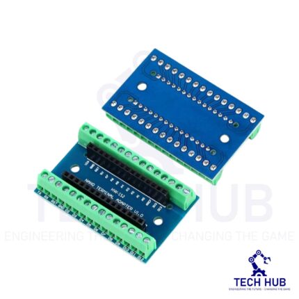
Arduino NANO Screw Terminal Expansion Board Shield
- Screw Terminal Shield for Arduino Nano Family.
- Compatible with Arduino Nano, Arduino Nano 33 IoT, Arduino Nano RP2040 Connect, Arduino Nano 33 BLE Sense, Arduino Nano 33 BLE, Arduino Nano Every, Arduino Nano ESP32
- Simplifies DIY projects by providing easy-to-use screw terminals.
- Color: blue
- Allows convenient and secure connections for Arduino Nano Applications.
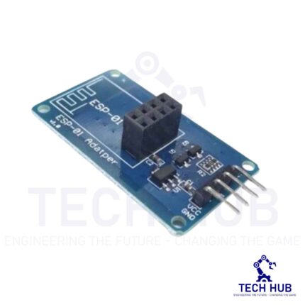
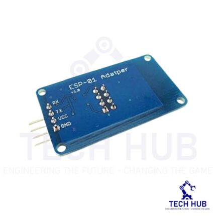
WIFI Serial Module ESP-01 Adapter Board (3.3V 5V)
The use of an ESP8266 with Arduino requires logic level translation of the UART signal, as provided by this easy 3.3 V – 5 V adapter. It makes the ESP-01 ESP8266 WiFi module the easiest WiFi transceiver for your Arduino (5 V).
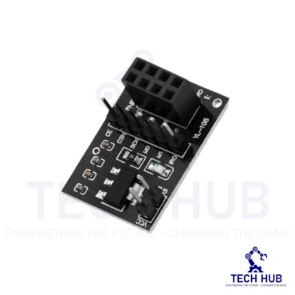
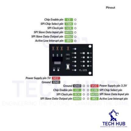
NRF24L01 Wireless Module Adapter Board
This 5V-3.3V VCC Adapter Board for NRF24L01 Wireless Module enables you to use NRF24L01-type transceivers on 5V systems like Arduino.
It regulates the 5V input to 1.9~3.6V DC and incorporates bypass capacitors for reliable operation. The NRF24L01 utilizes the Enhanced ShockBurst (ESB) protocol to support two-way data packet communication with packet buffering, packet acknowledgment, and automatic retransmission of lost packets.

Reviews
There are no reviews yet.