

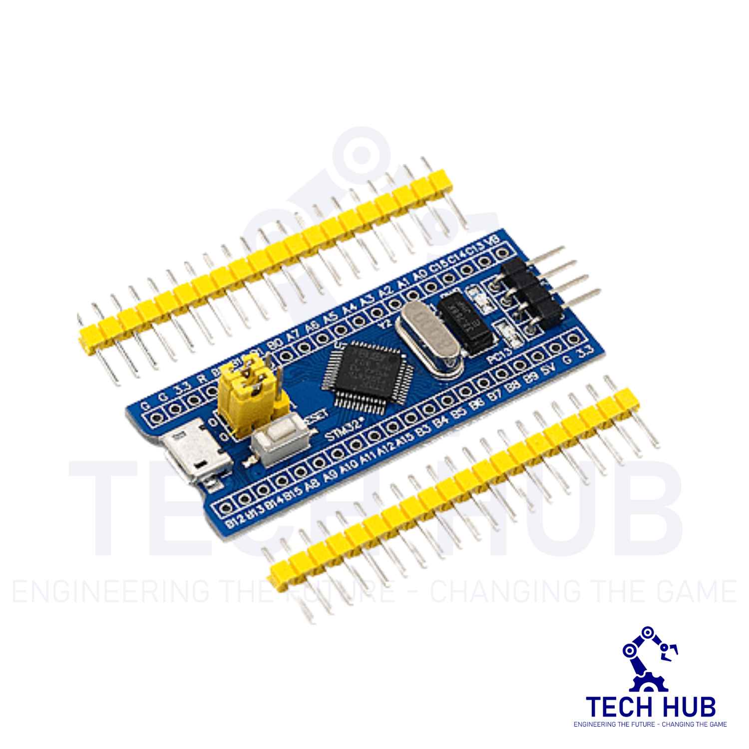
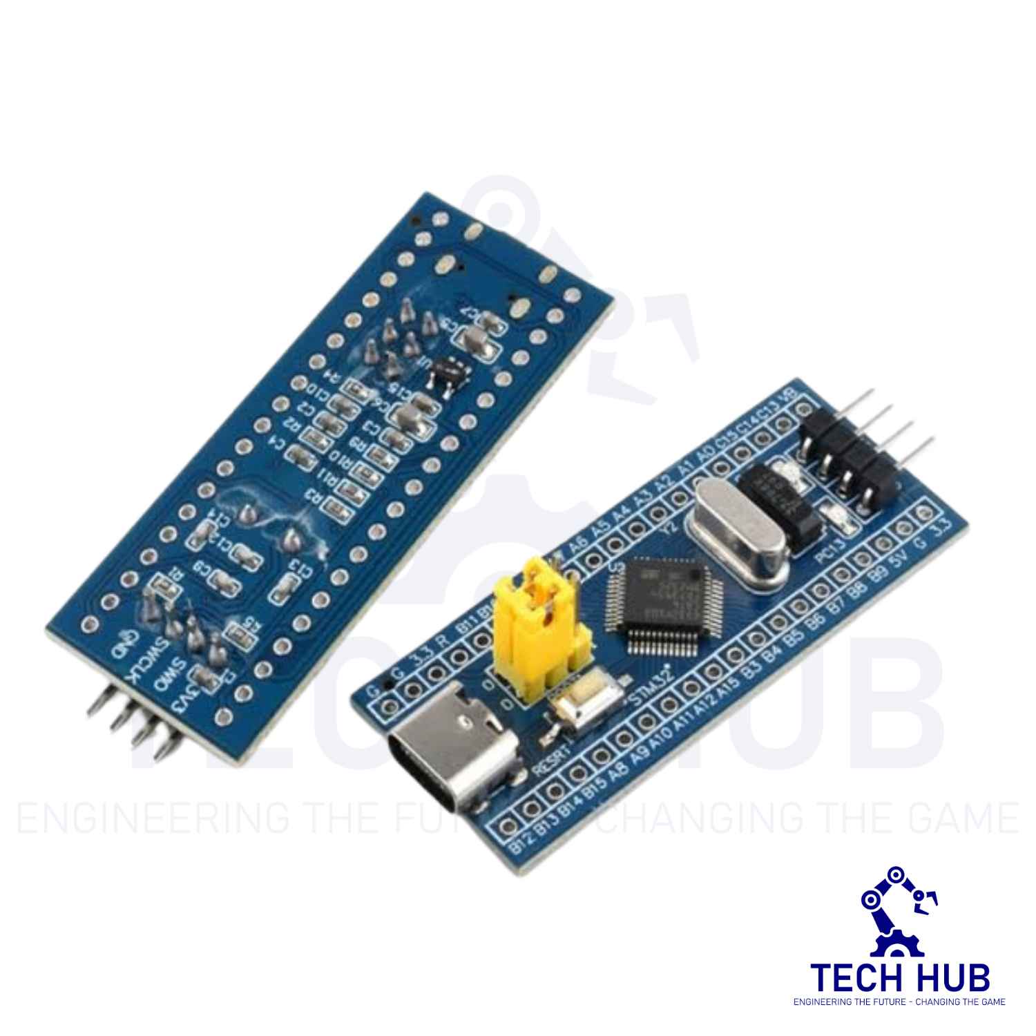


STM32F103C8T6 ARM STM32 Minimum System Development Board
250.00 EGP
- Number of pins: 48
- Kernel: ARM Cortex-M3
- Operating frequency: 72MHz
- Storage resources: 64K Byte Flash, 20KByte SRAM
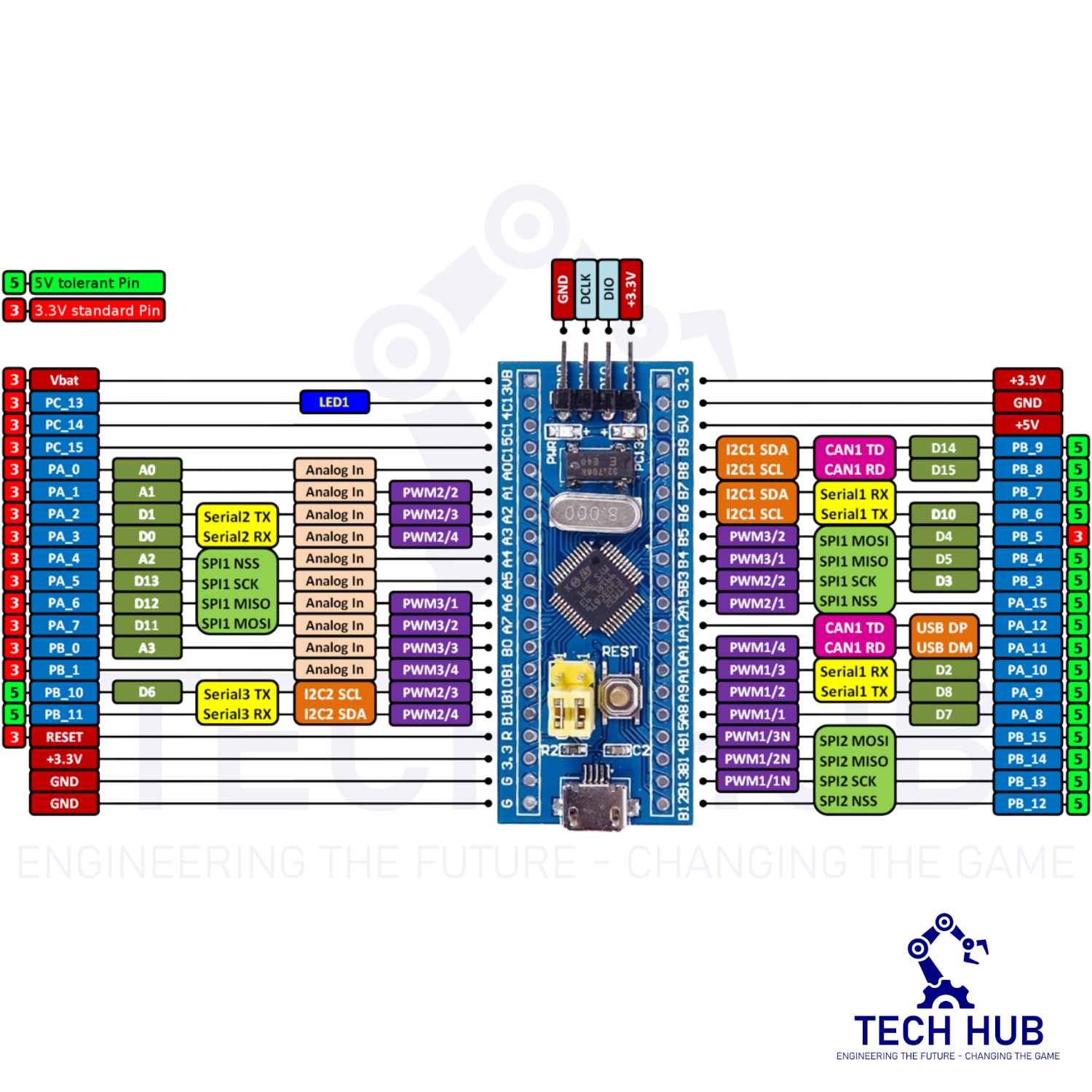
- Interface Resources: 2x SPI, 3x USART, 2x I2C, 1x CAN, 37x I / O ports,
- Analog-to-digital conversion: 2x ADC (12-bit / 16-channel)
- Timers: 3 general timers and 1 advanced timer
- Debug Download: Support JTAG / SWD debug interface to download, support for IAP.
- RT9193: 3.3V regulator chip, a maximum output of 300mA.
66 in stock
Description
Product Introduction
This is a core chip based on STM32F103C8T6 ARM core board.
Features:
- The board is based on the most basic MCU circuit, 8Mhz crystal circuit, and USB power supply circuit.
- The core board is divided into two rows leading to all the I / O ports.
- With SWD simulation debug download interface, simple and convenient, debugging speed.
- The use of the Mirco USB interface, you can do USB communication and power supply, The USB interface, is compatible with the ordinary mobile phone charger interface.
- RTC Crystal is easy to start and more stable.
- Keil can be used to compile, and IAR compile can be downloaded through the JLink or USART1 procedures, the procedures are the owner and debugging procedures.
Chip Description:
- STM32F103C8T6
- Package Type: LQFP
- Number of pins: 48
- Kernel: ARM Cortex-M3
- Operating frequency: 72MHz
- Storage resources: 64K Byte Flash, 20KByte SRAM
- Interface Resources: 2x SPI, 3x USART, 2x I2C, 1x CAN, 37x I / O ports,
- Analog-to-digital conversion: 2x ADC (12-bit / 16-channel)
- Timers: 3 general timers and 1 advanced timer
- Debug Download: Support JTAG / SWD debug interface to download, support for IAP.
- RT9193: 3.3V regulator chip, a maximum output of 300mA.
Interface Description:
- SWD interface: support for simulation, download and debug.
- Mirco USB interface: power supply and USB communication, do not support the download.
- USART1 interface: USART1 can be used to download the program, or use the USART1 for communication.
- MCU pin interface: leads all I / O port pins, easy to connect with peripherals.
- 5, 5V, and 3.3V power input and output interface: commonly used in external power supply, or with other modules for common ground treatment.
Other Device Description:
- Power LED (PWR): Power indicator status, can determine whether the power supply is stable.
- The user LED (PC13): to facilitate the I / O output test or indicate the program running.
- Start jumping choose programming mode: (1, the user flash memory 2, SRAM 3, system memory).
- Reset button: reset chip for the user program.
- 8M Crystal: The frequency can be set to make the system clocked at 72MHz.
- 32.768KHz Crystal: Available for built-in RTC, or for calibration.
Reviews (0)
Related products



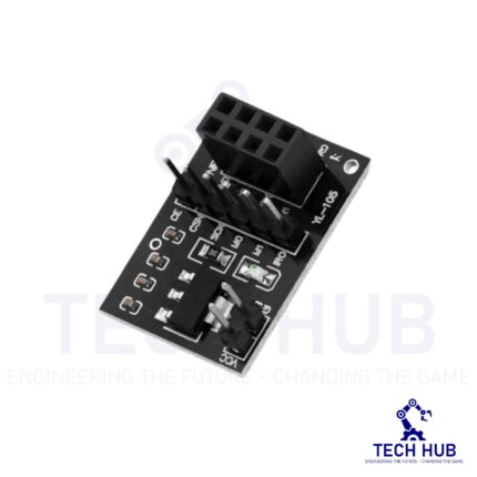
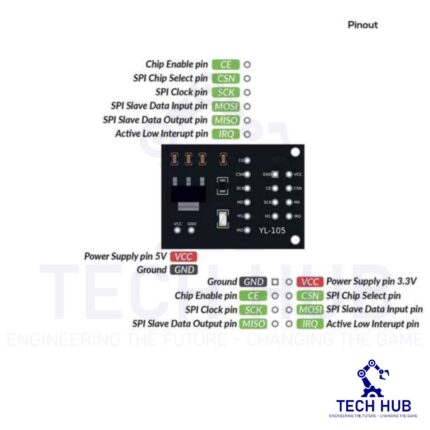
NRF24L01 Wireless Module Adapter Board
This 5V-3.3V VCC Adapter Board for NRF24L01 Wireless Module enables you to use NRF24L01-type transceivers on 5V systems like Arduino.
It regulates the 5V input to 1.9~3.6V DC and incorporates bypass capacitors for reliable operation. The NRF24L01 utilizes the Enhanced ShockBurst (ESB) protocol to support two-way data packet communication with packet buffering, packet acknowledgment, and automatic retransmission of lost packets.




Arduino UNO R3
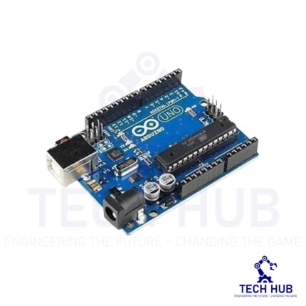
"Uno" means one in Italian and was chosen to mark the release of Arduino Software (IDE) 1.0. The Uno board and version 1.0 of Arduino Software (IDE) were the reference versions of Arduino, now evolved to newer releases. The Uno board is the first in a series of USB Arduino boards, and the reference model for the Arduino platform; for an extensive list of current, past or outdated boards see the Arduino index of boards.
Reviews
There are no reviews yet.